Introduction: Why Rust for PWM?
For the past few months, I’ve been on a mission to introduce a basic set of safe Rust abstractions to the Linux kernel’s PWM subsystem. If you’ve ever controlled the brightness of an LED or the speed of a fan, you’ve used PWM. It’s a fundamental part of how software interacts with hardware.
The primary goal was to see if I could build an API that lets developers write PWM drivers in 100% safe Rust, gaining all the benefits of the language’s memory safety and powerful type system. As a practical demonstration, I also wrote a functional PWM driver for the T-HEAD TH1520 SoC, which is found on the popular Sipeed Lichee Pi 4A board.
A quick note: This work, including the abstractions and the TH1520 driver, is currently in
linux-nextand is queued for merging in the upcoming kernel 6.19 merge window!
This wasn’t just a theoretical exercise; it had a very real goal: getting the temperature controlled CPU fan working on my board.
Building the Foundation: Safe Abstractions
The core of this work is a new rust/kernel/pwm.rs module. It provides abstractions that handle the tricky parts of interacting with the C side of the kernel, allowing driver authors to focus on their hardware logic. Based on extensive feedback from the kernel community, we settled on a few key principles.
1. Guaranteed Resource Management with RAII
One of the biggest risks in kernel development is leaking resources. To prevent this, the API uses a pwm::Registration RAII guard. This guarantees that every call to pwmchip_add is automatically paired with a pwmchip_remove when the object goes out of scope, completely eliminating a common class of bugs.
2. A Modern and Safe API
The main interface for a driver is the PwmOps trait. I based it on the modern “waveform” API, which is the current best practice for the subsystem. The best part? It moves all the unsafe logic into the abstraction layer. This means someone writing a new driver can implement the trait using 100% safe Rust.
A quick note on “100% safe”: If you peek at the TH1520 driver, you’ll spot an
unsafeblock to implementSendandSyncfor ourTh1520PwmDriverData.This isn’t a flaw in the API design, but a temporary implementation detail. It was only required because the kernel’s
Clktype didn’t implement these traits at the time. That fix has since landed, and thisunsafeblock is scheduled for removal in kernel 6.20.
The Journey: 16 Revisions
Getting code into the kernel is a highly collaborative process. This patch series went through 16 revisions based on invaluable feedback from maintainers and reviewers.
The initial versions used a simpler memory allocation model, but after discussions, I reworked it to use a much more robust “subclassing” pattern where the Rust driver data and the underlying C
pwm_chipare allocated in a single, contiguous block of memory. This is safer and more efficient.
This iterative process of feedback and refinement is what makes the kernel so robust.
A huge thank you to everyone who helped improve the API by reviewing code and suggesting improvements. Especially:
- Marek Szyprowski (Samsung Open Source Leader)
- Uwe Kleine-König (PWM Maintainer)
- Miguel Ojeda, Danilo Krummrich, & Daniel Almeida (Rust Maintainers)
- Drew Fustini (TH1520 Maintainer)
…and everyone else who helped with testing and feedback.
You can follow the whole journey and see the final v16 patch series on the kernel mailing list.
Diving into the Driver: How It Works
So how does this all come together in a real driver? Let’s look at the TH1520 driver to see how these new abstractions make writing a driver cleaner and safer.
1. The Driver’s State: Th1520PwmDriverData
First, we define a struct to hold our driver’s state. This is where we’ll keep our memory-mapped registers (iomem) and our clock (clk).
Before we look at the code, we need to talk about Pin. In kernel drivers, we often build complex data structures. Sometimes, these structures must never move in memory once they are created (for example, if they are involved in async operations or have internal pointers to their own fields).
If we just moved such a struct, those internal pointers would become invalid and point to garbage.
Pin is a mechanism in Rust that “pins” data to its location in memory. It’s a guarantee to the compiler that the data’s address will not change. This is why you’ll see #[pin_data(PinnedDrop)] and #[pin] in the struct, and why our probe function returns impl PinInit - it’s all part of this safety first “pinning” initialization.
|
|
Notice the impl PinnedDrop block at the bottom. The drop function is called automatically when our driver is unbound. Here, we safely disable our clock. This is a perfect example of the RAII principle at work - cleanup is guaranteed.
2. The probe Function: Setting Up the Driver
The probe function is the entry point for our driver. This is where the new abstractions really shine.
|
|
Let’s break this down:
-
Lines 13 & 16: We acquire and enable our clock resource, using Rust’s
?for clean error handling. -
Lines 23-26: We initialize our
Th1520PwmDriverDatastruct. Thetry_pin_init!macro is a “pinned initializer” that safely allocates our struct and maps the I/O memory (iomap_sized). -
Lines 30-34: This is the “magic” because it hides a huge amount of C boilerplate. In a C driver, you would have to:
- Manually allocate the C
pwm_chipstruct. - Manually allocate your
Th1520PwmDriverDatastruct. - Manually link them together with
dev_set_drvdata. - Manually create a
pwm_opsvtable (a struct full of function pointers) and point it to your C functions.
Here,
pwm::Chip::newdoes all of that for us. It creates the C struct, links our Rust data, and automatically sets up the FFI bridge so the kernel can call our safePwmOpstrait methods. - Manually allocate the C
-
Line 39: We call
pwm::Registration::register. This single line handles registering thepwm_chipwith the kernel. The returned object is an RAII guard that, as mentioned before, ensurespwmchip_removeis called on cleanup.
That’s it. All the complex C side boilerplate of setting up the pwm_chip struct, managing memory, and hooking up ops is handled by the abstraction layer.
3. The PwmOps Trait: The Safe Hardware Logic
Now for the best part. All of our hardware-specific logic is implemented in the PwmOps trait. This code is 100% safe Rust.
The code block below only shows the two main “translation” and “write” functions, but the full implementation handles all four required callbacks.
|
|
Here, we implement the four main callbacks that form a “full loop” for the hardware.
round_waveform_tohw: This is the “translation” function. It takes a generic “waveform” request (period and duty in nanoseconds) from the PWM subsystem and translates it into the specific register values our hardware understands (e.g.,period_cycles).write_waveform: This is the function that does the work. It takes the hardware-specific values we just calculated and writes them to the actual memory-mapped registers to change the fan speed.read_waveform: This reads the current values from the hardware registers and returns them as a hardware-specific struct.round_waveform_fromhw: This is the “reverse translation” function. It takes the hardware struct fromread_waveformand translates it back into generic nanosecond values that the kernel’s sysfs interface can understand and report to a user.
The abstraction layer handles all the unsafe pointers, locking, and C interop. We just get to write safe Rust that manipulates our hardware.
The Result: A Spinning Fan
The outcome of all this work is a new Rust driver, the necessary Device Tree bindings, and ultimately, a correctly functioning, temperature controlled fan on the Lichee Pi 4A.
It’s rewarding to see the fan speed up as the chip gets warmer, all controlled by a driver written in Rust. 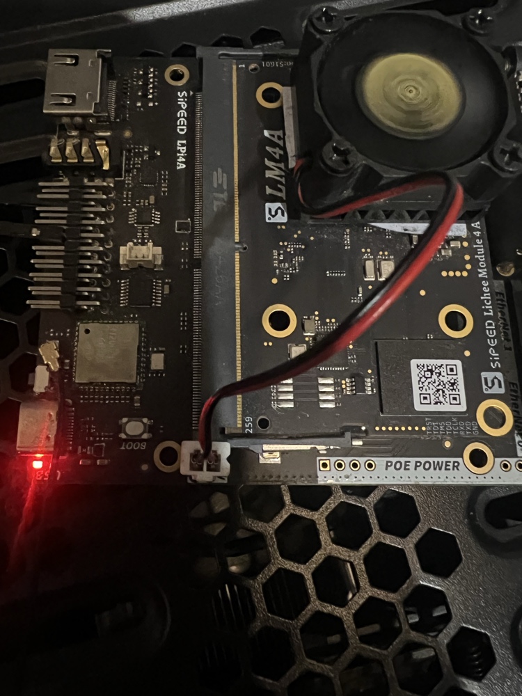
This work lays a foundation for future Rust based PWM drivers and is another step forward for Rust in the Linux kernel.